Monday, Aug 27, 2018
IoT with ESP8266 - Part 2: Flashing
Let me show you how to flash new firmware on ESP2866 ESP-01 Microcontroller. In this post, you will learn some basic stuff about digital circuitry and ESP-01, as well as how to create a simple breadboard assembly.
To make something useful of your brand new ESP8266 module, you have to flash new firmware to it. In my previous post, I have explained fundamentals about the device and what kind of software it can run. Now I will walk you through the process of flashing new software on ESP-01. I chose it because it’s small, cheap and interesting to work with, and I chose ESPEasy firmware because we’ll be using it in my next blog post, and it’s easy to check if the flashing went well.
Requirements
First, you will need some hardware…
- 1x ESP8266 ESP-01
- 1x FTDI FT232RL USB to TTL Serial Adapter - 3.3V and 5V
- 1x USB cable Mini type B to Type A
- 1x Breadboard
- 2x Resistor 10KΩ
- Some breadboard wires
… and software:
ESP8266 ESP-01
ESP-01 is the smallest of all ESP modules. It exposes only 8 pins in a 2x4 layout - of which only 2 are GPIO pins, so there are practical limits of how much sensors or actuators can be attached to it. There is a way to expand the number of available GPIO ports using IO expander device like MCP23017, or by using I2C protocol for communicating with multiple devices based on addressing, but this is out of scope for this post. ESP8266 supports up to 16MB of flash storage, and this module comes in 2 variants based on storage capacity. The older one has 512Kb (blue board), but it’s deprecated and replaced with 1Mb version (black board). The latter supports OTA (Over The Air) firmware update using WiFi connection rather than serial. It’s important to remember that ESP8266 runs on 3.3V unlike Arduino and most of its sensors, so you have to be extremely careful when attaching it to a power supply. Applying voltage higher than 3,6V results in unrecoverable damage. Also, RX pin (UART Receive) does not tolerate more than 3.3V, so if you need to set up a communication with other devices (e.g. Arduino), you need to add a voltage divider.

| PIN | Abbreviation | Description |
|---|---|---|
| 1 | VCC | Power 3.3V |
| 2 | RX | UART Receive (warning, this pin is NOT 5V tolerant) |
| 3 | RST | Reset (low – Reset, high- Normal) |
| 4 | GPIO 0 | Must be high on boot, low for flash update. |
| 5 | CH-PD | Must be high for normal operation (Chip enable) |
| 6 | GPIO 2 | GPIO 2 (can be left in floating state) |
| 7 | TX | UART Transmit |
| 8 | GND | Ground |
FTDI FT232RL USB to TTL Serial Adapter
This adapter provides connectivity from USB to serial UART interface, and it has a voltage regulator for 3.3V or 5V output. It is used for communication between your computer and ESP8266 using serial connection. Also, we can use the adapter to power up the ESP8266 with 3.3V - there is a jumper on the adapter that has to be set for 3.3V output.

Breadboard
The breadboard is used for fast circuit prototyping without soldering of electronic components. You just plug components on it and use special connection wires to connect them. More information on how to use the breadboard can be found here. It is possible to flash without one, but it would be extremely challenging to connect all the components properly, so please get one.
PULL-UP and PULL-DOWN resistors
Pull-up and pull-down resistors are common when working with microcontrollers. They make sure that PIN state has a logical value that can be determined by the system. There are 3 states that can be achieved using this technique:
- High state – by connecting to the power (VCC),
- Low state – by connecting to the ground (GND), and
- Floating – by not connecting to anything.
When ESP8266 is powering up, some pins are checked for their state. Based on the outcome, MCU will (or won’t) run in a certain mode. Pins that are not used can be left in floating state (unconnected). Next 3 pins must have specific values when booting in normal or in flash mode:
| PIN | Normal Boot | Flashing |
|---|---|---|
| RST (Pin 3) | high | high |
| GPIO 0 (Pin 4) | high | low |
| CH-PD (Pin 5) | high | high |
For more details on pull-up and pull-down resistors check this excellent tutorial.
Breadboard adapter for ESP-01
The first step is to assemble the circuit correctly. Unfortunately, ESP-01 is not breadboard-friendly, which means it cannot be plugged in directly to the breadboard (the space between two rows of pins is too narrow and cannot fit in the middle). You can make a nice little adapter for it, or connect it using male to female wires. I made this simple adapter in about 15 minutes.

Assemble and make a circuit
Next, you have to connect all parts to the breadboard and assemble it using the diagram below. Notice that I couldn’t position the ESP module on the breadboard, but had to simulate adapter to be able to connect all other elements. That connection is represented by white wires, and pins on the breadboard match ESP module pinout.

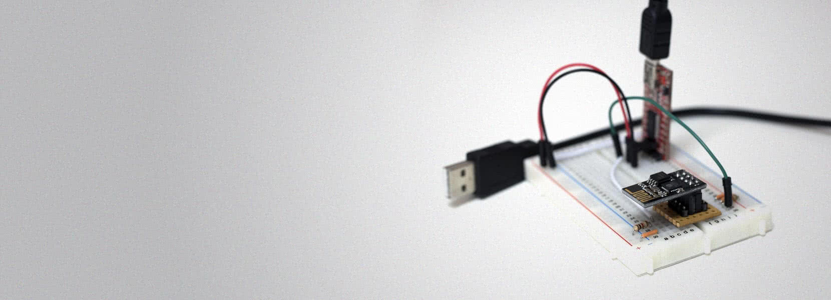
Just follow the connections on the diagram - I set colors to match its purpose. Here is how the final breadboard setup looks like.
![Final setup]BBSetup.jpg)
Now you are ready to flash some firmware!
Connect to PC and flash
First, you need to download required drivers, tools, and firmware. Install drivers for FT232RL, and prepare flashing tool and firmware. Double check that you switched jumper selector to 3.3V, then plug USB cable to FT232RL, then to your PC. FT232RL will be recognized by the PC, drivers will automatically install, and new com port will appear. You should see the red notification light on both FT232RL and ESP8266 module. Run esp8266_flasher.exe and select the correct com port and firmware image. Do not change the address because you want to flash the entire firmware from the first flash address. Now click Download.

Wait for a minute until you get the notification message that flashing is successfully finished. Sometimes, due to cheap FTDI adapters, the flash process fails with an error. If you experience that, just hit download again until it finishes successfully. Sometimes it takes 2-3 attempts to do it. I guess you’ll want to check if the flashing worked, right? To do that, unplug USB from your PC, and then enable normal booting mode simply by setting the GPIO_0 pin to HIGH. Plug out the GPIO_0 resistor from GND and put it into VCC. Plug USB in your PC and check if the blue LED light on ESP8266 module started blinking.
Next, use your mobile or any device with WiFi capabilities to scan WiFi networks. You should see an Access Point with SSID name ESP_0, which you can connect to. If asked for a password, enter “configesp”. The default IP address of the device is 192.168.4.1, and you can open it in the browser. Congratulations, you are now looking at ESPEasy application.
For my next post, I am preparing a simple IoT solution with a central hub that runs Domoticz on Raspberry PI Zero W, and one ESP8266 with the ESPEasy application that we just flashed. We will add a temperature sensor and a relay switch on it so that we can create different applications like remote outlet switch and automated thermostat.