Monday, Aug 27, 2018
IoT with ESP8266 - Part 1: Basics
Everybody talks about Internet of things, smart devices, and smart home. If you want to make your own home automation system, check out this brief introduction to Internet of things with an ESP8266 microcontroller.
Internet of Things can be described as a network of mutually connected physical devices embedded with sensors, actuators, and software, which can be used for collecting and exchanging data. In short, any standalone device connected to a network and capable of running applications and interacting with the physical world can be considered as an IoT device.
With the fast development of technology and mobile computing, IoT became a very popular concept in the last few years. Smart city, smart health (eHealth), and Smart Home are just a few ideas designed to utilize those new technologies and, in some way, make our life easier. Devices like smartphones, smart TV’s, and home appliances like smart refrigerators connected to the Internet are perfect examples of how traditional devices can be upgraded to meet future needs. Now you can program your fridge to check if you have enough milk, and if you don’t, it can automatically make an order with delivery from your local store (maybe even by a drone).
Home automation systems recently became popular among companies that make high-tech home appliances. There are products like Belkin’s WEMO that can turn your ordinary house to a smart one. That’s exactly what interests me - I wanted to create a similar system using cheap and easy obtainable electronic parts. In this blog series, I will write about Home automation and how to create simple IoT devices using an ESP8266 microcontroller. This post will cover the basics about ESP8266 and what makes it tick. Later posts will include detailed and practical examples on how to create devices like sensors, switches, etc. Some basic knowledge about electronic is required, but I will try to explain every step in detail so that anyone can follow.
About microcontrollers
Microcontroller (MCU) is essentially a simple computer on a single integrated circuit with one or more processor units (CPUs), along with memory and programmable input/output (I/O) peripherals. In modern terminology, it is known as a System on a Chip (SoC). Microcontrollers are with us for more than 40 years and can be found in most digital circuits. Today, there are hundreds of SoCs available on the market, and the most popular one is based on Arduino.
Arduino project was created in 2005 to provide a low-cost and easy way for novices and professionals to create devices that interact with their environment using sensors and actuators. It is a powerful platform and DIY (Do It Yourself) community adopted it very fast, but it lacked one important feature - a network connection. That’s where ESP8266 kicks in, with its native TCP/IP support over WiFi network.
ESP8266 SoC is created by Espressif Systems, a Chinese company based in Shanghai. Mass production started in 2014, when several OEM’s recognized it’s potential and created breakout boards for developers to use. At first, Arduino folks started using it as a cheap WiFi interface for their boards, but soon they figured out that the platform is powerful enough to be used on its own. Now, there is a fast growing community of developers for ESP8266, and its successor, ESP32.
ESP8266 SoC
ESP8266 SoC packs a single core 32-bit processor clocked on 80-160 MHz, with 64 KB + 96 KB of RAM, and supports 802.11 (WiFi) standard. It supports a fair number of communication protocols and can be connected to a large number of sensors, actuators or other MCU’s. There is a total of 17 available GPIO (General Purpose In/Out) pins, of which some are dedicated, and some are multiplexed with other functions. It supports UART, SPI, I2C, and full TCP/IP stack over WiFi.
Hardware specification
| Feature | Description |
|---|---|
| Input voltage | 3.3V |
| Current consumption | 10uA – 170mA |
| Flash memory | External QSPI flash 512 KB to 4 MB (Max 16MB) |
| CPU | Tensilica L106 32 bit (RISC, single core) |
| CPU Clock | 80-160MHz |
| RAM | 64 KB instruction, 96 KB data |
| GPIO pins | 17 (multiplexed with other functions) |
| ADC (Analog to Digital Converter) | 1 (10 bit) |
| WiFi support | b/g/n |
| Network protocols | IPv4, TCP/UDP/HTTP/FTP |
| Maximum concurrent TCP connections | 5 |
Full hardware specification can be downloaded here.
There are several breakout board styles, and they differ in the number of exposed GPIO pins, and EEPROM chip capacity (storage memory). I will focus on most common boards: ESP-01 and ESP-12. Some manufacturers created developer friendly boards based on ESP-12 package for fast application development and prototyping. One of those boards is NodeMCU development kit. Here I must point out that all ESP boards I will use are based on ESP8266 SoC, but can differ in storage (flash) capacity, size or associated circuitry.
ESP-01
ESP-01 is the smallest of all available boards using ESP8266 SoC. It exposes only 8 pins (two of them are GPIO), and it was one of the first boards available. Do not be discouraged by the number of pins. If you intend to create a small and cheap device with simple sensor or switch (relay), this could be an ideal choice. Also, it is more difficult to use it since it doesn’t have any supporting circuitry, and can’t work on its own. That’s why I decided to use that one in my next blog post.

ESP-12
This is the most popular board available. It exposes 9 GPIO pins and 1 ADC (Analog to Digital Converter). With a large number of exposed pins, this board can be used in most projects, and it can be connected to many different sensors and devices. Same as ESP-01, it doesn’t have supporting circuitry or even exposed pins to connect to something. To use it, you have to solder it to a special board or add a few pins.

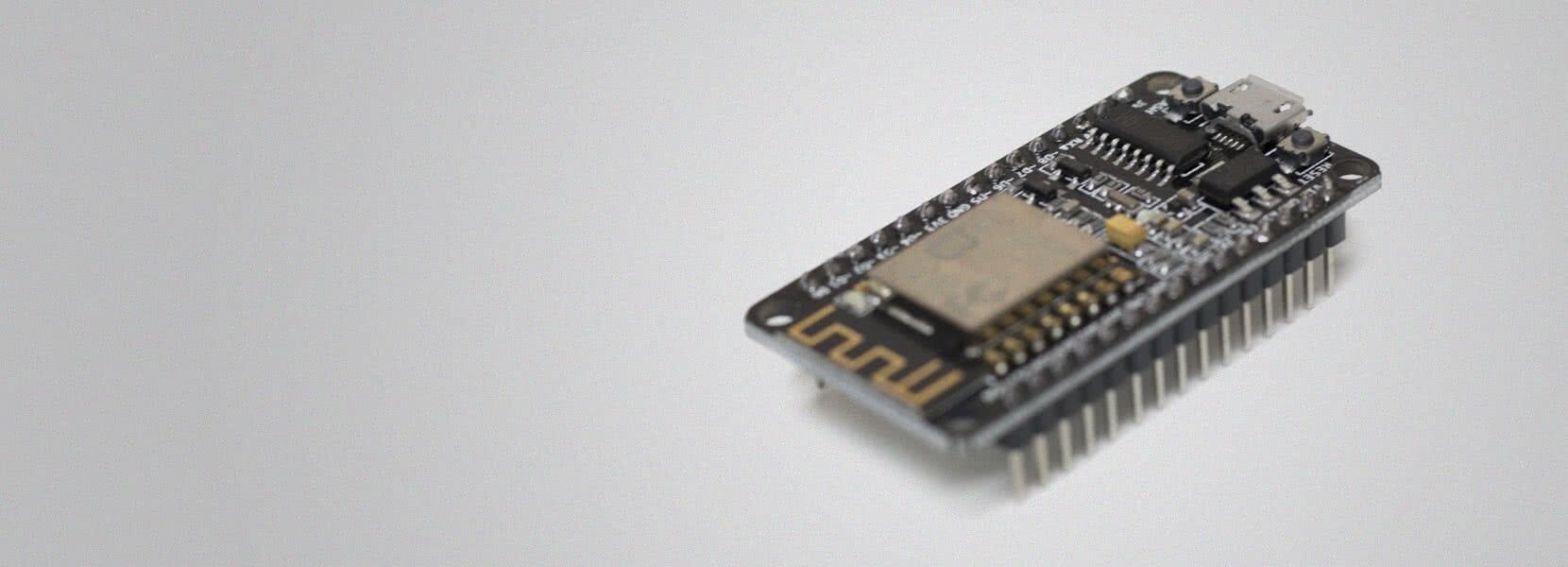
NodeMCU Development Kit
While previous boards need some external circuitry in order to work properly, NodeMCU board is plug and play. The board includes USB to Serial adapter, voltage regulator, and buttons for reset and flash mode. Basically, all you need to do is connect it to a computer (you have to install the drivers first), and you are ready to go. NodeMCU board comes with preloaded firmware which runs a Lua based script interpreter.

ESP8266 programming
By default, ESP boards are preloaded with AT firmware. With it, they are mostly used for creating serial to WiFi connection and can act as WiFi network interface for any other microcontroller. In October 2014, Espressif released SDK (Software Development Kit) that allowed programmers to program the MCU and create new firmware for it. Using the SDK, it’s possible to write a program that runs natively on the device with full access to GPIO pins and WiFi through APIs. The code can be written in C, C++ or Assembler language, compiled and saved to the device in a process called flashing. There are now many (mostly open source) projects that allow ESP8266 SoC to be used as a standalone device, either as higher level programming language interpreters (Lua, JavaScript or BASIC) or as software written for specific purposes, like Home Automation (ESPEasy). Arduino developers can use their IDE to write native applications for this SoC.
NodeMCU Development Kit with Lua
NodeMCU firmware is actually Lua script interpreter based on eLua project. It enables the developer to write programs for ESP8266 without compiling it. The script just needs to be saved to a chip, and it can run on startup. The source code is available on GitHub, and documentation can be found here.
JavaScript and ESPRUINO
Originally, the espruino project was written for ARM processors but is being ported to ESP8266. It runs a JavaScript interpreter.
MicroPython
MicroPython is based on a small subset of Python 3 language and is optimized for microcontrollers. It’s mainly used with pyboard but is ported to other SoCs as well. It runs as a low-level operating system so commands can be executed immediately or from a script. Documentation on MicroPython for ESP8266 can be found here, and firmware downloaded from here.
BASIC with MMISCOOL’s Basic Interpreter
This firmware utilizes BASIC interpreter with one unique and interesting feature. The system runs a web server with editor interface in which you write the code, save it, and then run it. The result is then rendered to a web page by the interpreter. This way you can create nice UI that runs directly on the device with access to GPIO pins. For example, you can create a button as on/off switch to control relay.
ESPEasy
ESPEasy is a home automation software for ESP8266. It’s an open source program that runs as web service and supports a large number of sensors and actuators. It can be used as standalone or with one of the home automation system hubs like Domoticz. I will cover this system in one of the future blog posts, and show you how to create one small temperature sensor and relay switch using ESP-01 and control it using Domoticz.
This covers the basics about ESP8266. In my next post, I will show you how to create supporting circuitry for the ESP-01 board, and how to flash it with the new firmware. In the meantime, here are a few links to keep you busy: